
SAE Flywheel Housing Sizes: Dimensions & Compatibility

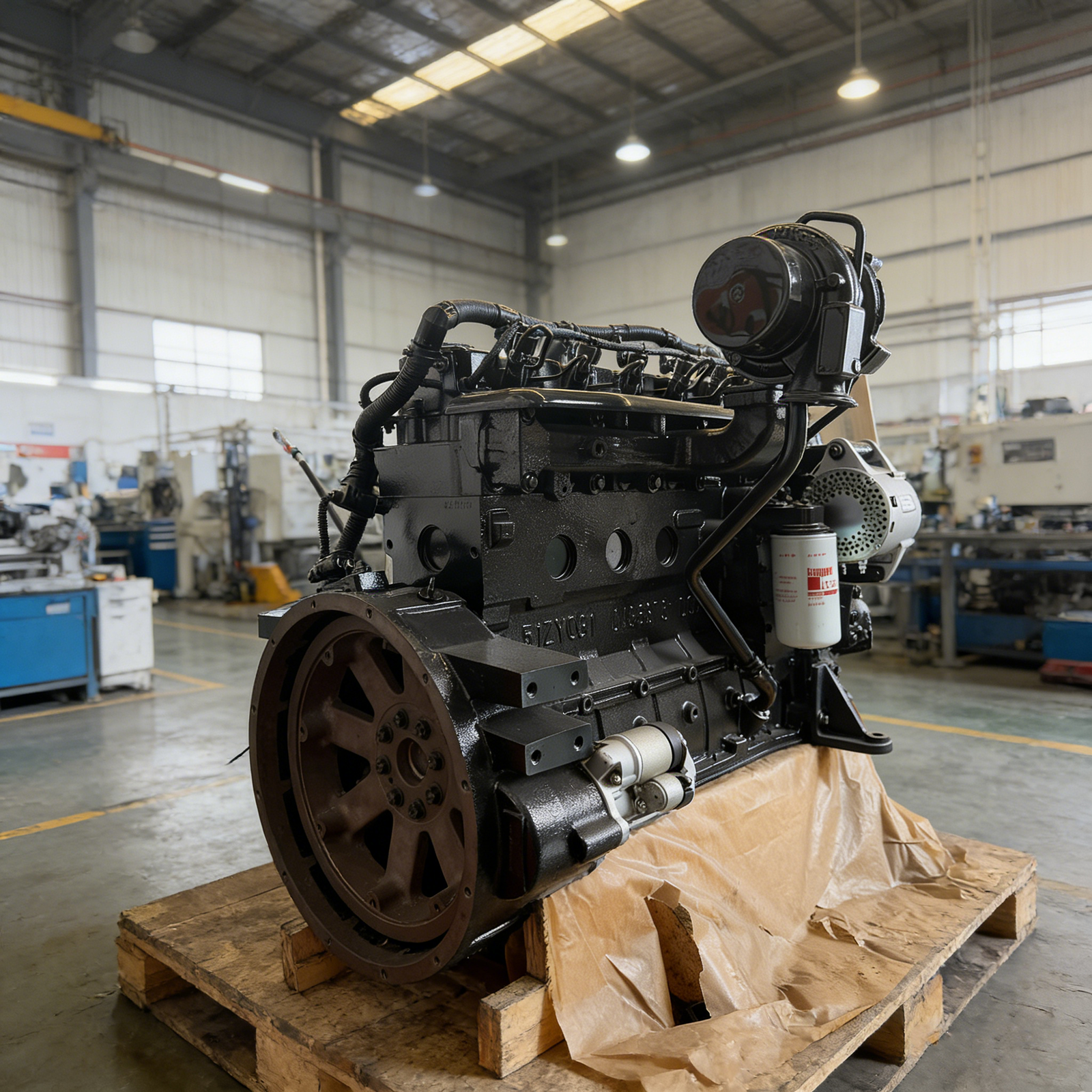
SAE flywheel housing sizes identify the standardized mounting interfaces used to connect diesel engines with transmissions, generator drives, clutches, and industrial equipment. Common SAE sizes include #1, #2, #3, #4, #5, and #6. Each designation specifies a nominal pilot diameter, mounting bolt circle, and related dimensions under SAE J617. A smaller SAE number generally indicates a larger housing interface.
To identify the correct size, measure the machined pilot bore, verify the mounting-hole pattern, and check the applicable housing drawing. Matching the SAE number is an important first step, but it does not guarantee that the flywheel, coupling, or driven equipment will fit.
SAE Flywheel Housing Size Chart
SAE J617 establishes dimensional requirements for engine flywheel housings and mating transmission housing flanges.
The standard helps manufacturers use consistent mounting interfaces across different engine and equipment designs.
Common SAE Flywheel Housing Dimensions
| SAE Size | Pilot Bore Diameter | Bolt Circle Diameter | Mounting Holes |
|---|---|---|---|
| SAE #1 | 511.18 mm / 20.125 in | 530.22 mm / 20.875 in | 12 |
| SAE #2 | 447.68 mm / 17.625 in | 466.72 mm / 18.375 in | 12 |
| SAE #3 | 409.58 mm / 16.125 in | 428.62 mm / 16.875 in | 12 |
| SAE #4 | 361.95 mm / 14.250 in | 381.00 mm / 15.000 in | 12 |
| SAE #5 | 314.32 mm / 12.375 in | 333.38 mm / 13.125 in | 8 |
| SAE #6 | 266.70 mm / 10.500 in | 285.75 mm / 11.250 in | 8 |
These are nominal dimensions from SAE J617-based dry-type housing tables. Actual tolerances, threads, pilot depth, and alternative arrangements require verification against the applicable standard and engineering drawings.
Notice that SAE #1 has a larger pilot bore than SAE #3. The numbering does not increase with physical size.
Larger interfaces, including SAE #0 and #00, are also defined for other applications.
The housing designation identifies the mounting interface rather than the engine’s horsepower or displacement.
Two engines with different power ratings may use the same SAE housing size, while different versions of one engine family may have different housings.
How to Identify and Measure an SAE Flywheel Housing
An SAE size marking or engine installation drawing is the preferred identification source.
When those details are unavailable, several physical measurements can help establish the housing size.
Measure the Pilot Bore
The pilot bore is the machined circular opening in the flywheel housing.
It locates the mating transmission housing or adaptor concentrically with the engine’s rear mounting interface.
Measure the bore using an appropriate precision instrument. Avoid taking measurements from rough casting surfaces or damaged edges.
For example, a nominal pilot diameter of 409.58 mm corresponds to SAE #3.
A diameter of 447.68 mm corresponds to SAE #2.
These dimensions identify the nominal interface but do not establish whether the housing remains within acceptable machining tolerances.
Verify the Bolt Circle and Hole Pattern
The bolt-circle diameter is the diameter of the imaginary circle passing through the mounting-hole centers.
It is not the outside diameter of the flywheel housing.
For SAE #3, the nominal bolt-circle diameter is 428.62 mm.
Count the mounting holes and check their positions after measuring the bolt circle.
Several SAE sizes share the same hole count. Therefore, twelve mounting holes alone cannot establish the housing designation.
Thread specifications must also be verified because SAE housings may use different thread arrangements.
Check Housing Depth and Mounting Face
The axial relationship between the housing face and engine crankshaft is another important measurement.
This determines whether the driven equipment can be connected with the correct shaft engagement and operating clearance.
SAE J617 includes axial dimensional requirements for relevant housing arrangements.
The mating component must also meet the manufacturer’s alignment and mounting-face requirements.
An incorrectly positioned adaptor can create problems even when the pilot bore and mounting bolts appear to fit.
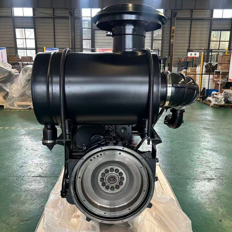
SAE Flywheel Housing vs Flywheel Size: Why Both Matter
Flywheel housing size and flywheel size are separate specifications.
The flywheel housing establishes the structural mounting interface. The flywheel transfers torque from the crankshaft to the driven equipment.
SAE J617 addresses housing interfaces, while SAE J620 defines flywheel dimensions for specified industrial applications.
| Feature | Flywheel Housing | Flywheel |
|---|---|---|
| Primary function | Mount and locate driven equipment | Transfer engine torque |
| Relevant standard | SAE J617 | SAE J620 for covered applications |
| Important dimensions | Pilot bore, bolt circle, mounting face | Drive interface, bolt pattern, axial geometry |
| Main compatibility concern | Mounting and alignment | Coupling or clutch engagement |
| Same SAE designation required? | Not necessarily | Must match the intended drive arrangement |
An engine fitted with an SAE #3 flywheel housing does not automatically have an SAE #3 flywheel.
This distinction becomes important when connecting an alternator, marine gearbox, transmission, or hydraulic pump drive.
For example, the housing may accept an alternator adaptor while the flywheel does not match the alternator’s drive disc.
The assembly cannot be considered compatible until both interfaces have been verified.
SAE Flywheel Housing Compatibility in Diesel Engine Applications
Industrial engine installations introduce different mechanical requirements depending on the driven equipment.
The SAE designation helps identify the mounting interface, but it does not replace a complete installation assessment.
Diesel Generator Sets
Many generator sets use a direct-coupled alternator connected to the engine through a mounting adaptor.
The adaptor must match the engine’s flywheel housing, while the alternator drive connection must match the flywheel.
In a single-bearing alternator arrangement, correct alignment and axial positioning are particularly important.
An incorrect connection can introduce unwanted loads, vibration, or premature coupling and bearing wear.
The engine’s rated speed and alternator requirements must also be checked independently of the SAE housing size.
Industrial Pumps and Power Take-Offs
Industrial pumps may be driven through a gearbox, clutch, or power take-off attached to the engine housing.
These arrangements require suitable mounting geometry and adequate torque capacity.
A housing with the correct bolt pattern does not guarantee that the connected gearbox can handle the engine’s maximum torque.
For a pump operating under variable loads, coupling design and torsional characteristics can be as important as mounting dimensions.
The equipment manufacturer’s installation drawing should define the required clearances and mechanical ratings.
Construction Machinery
Excavators, loaders, and other construction equipment often have limited space around the engine’s rear mounting interface.
An engine with suitable horsepower may still require a different flywheel housing or adaptor arrangement.
For example, Kangjin Power lists several configurations of the Cummins QSB6.7 diesel engine for construction and industrial applications.
These engines have different rated outputs, but horsepower does not determine the fitted SAE housing.
The exact configuration must be confirmed from its engine serial number, housing part number, or installation drawing.
The same consideration applies to the Cummins 6CTA8.3 diesel engine, which is used in heavy-duty industrial machinery.
Even when two engines belong to the same family, their rear mounting arrangements may differ.
Engine Replacement Projects
Replacing an existing engine requires more than matching power and overall engine dimensions.
A replacement may have a different flywheel housing, flywheel, crankshaft connection, or starter arrangement.
Before treating two engines as mechanically compatible, verify:
- SAE flywheel housing designation and pilot diameter.
- Mounting-hole locations, threads, and bolt-circle diameter.
- Flywheel specification and drive connection.
- Housing face and crankshaft axial dimensions.
- Coupling or clutch torque capacity.
- Input-shaft engagement and required operating clearance.
- Engine mounting positions and alignment tolerances.
A properly designed adaptor can sometimes connect different SAE interfaces.
However, an adaptor must also preserve alignment, shaft engagement, structural integrity, and adequate clearances.
It should not be treated as a universal solution for mismatched components.
Why Matching SAE Housing Numbers May Still Cause Installation Problems
Matching SAE dimensions is necessary for many direct-mounted installations, but several issues can remain.
One is housing alignment. The mounting face and pilot bore must meet the applicable runout requirements relative to the engine crankshaft.
Excessive runout can contribute to vibration, accelerated coupling wear, and increased bearing loads.
Another issue is axial positioning. If the driven shaft or coupling sits too far forward or backward, components may bind or fail to engage correctly.
A third concern is mechanical capacity. The housing may physically fit while the clutch, gearbox, or coupling is unsuitable for the engine’s torque and duty cycle.
These problems are especially relevant when upgrading older equipment.
Kangjin Power’s Cummins engine models guide explains differences among several B Series and QSB platforms.
When comparing those engines for replacement, use the full engine model and serial number to identify the appropriate installation documents.
The practical rule is straightforward: a matching SAE housing number confirms the nominal mounting interface, not complete drivetrain compatibility.
Frequently Asked Questions
What are the most common SAE flywheel housing sizes?
Common dry-type industrial housing sizes include SAE #1, #2, #3, #4, #5, and #6. Larger SAE sizes such as #0 and #00 are also defined. The correct size depends on the engine’s housing configuration and the driven equipment.
What is the difference between SAE #2 and SAE #3 flywheel housings?
SAE #2 has a nominal pilot diameter of 447.68 mm and a bolt circle of 466.72 mm. SAE #3 has a smaller pilot diameter of 409.58 mm and a bolt circle of 428.62 mm.
Is SAE #3 larger than SAE #2?
No. SAE #2 is physically larger than SAE #3. Smaller numbers generally indicate larger SAE housing interfaces.
Can different SAE flywheel housing sizes be adapted?
Yes, in some applications. A properly engineered adaptor may connect different housing interfaces, but alignment, axial clearance, coupling capacity, and mounting strength must be verified.
Does SAE flywheel housing size determine flywheel size?
No. Flywheel housing and flywheel dimensions are governed by separate specifications. Both must be checked when connecting an engine to a clutch, transmission, alternator, or pump drive.
How do I identify the SAE housing size on a Cummins engine?
Check the engine’s installation documentation, serial number, and flywheel housing part number. If documentation is unavailable, measure the pilot bore, bolt circle, hole arrangement, and relevant axial dimensions.
Summary
SAE flywheel housing sizes provide standardized mounting interfaces between diesel engines and driven equipment. Each designation defines key dimensional relationships, including the pilot diameter and mounting bolt circle.
For generators, industrial pumps, transmissions, and construction machinery, matching the housing number is only part of the compatibility check. Flywheel geometry, coupling design, alignment, axial clearances, and mechanical ratings also affect the installation.
The most reliable approach is to verify the applicable SAE J617 dimensions alongside engine-specific drawings and the driven equipment manufacturer’s requirements. This reduces the risk of incorrect mounting, alignment problems, and unnecessary modifications during installation or engine replacement.

